Combination Stereomicroscope and Vic-3D digital image correlation

Application examples of a special stereomicroscope in combination with Vic-3D digital image correlation on electronic components.
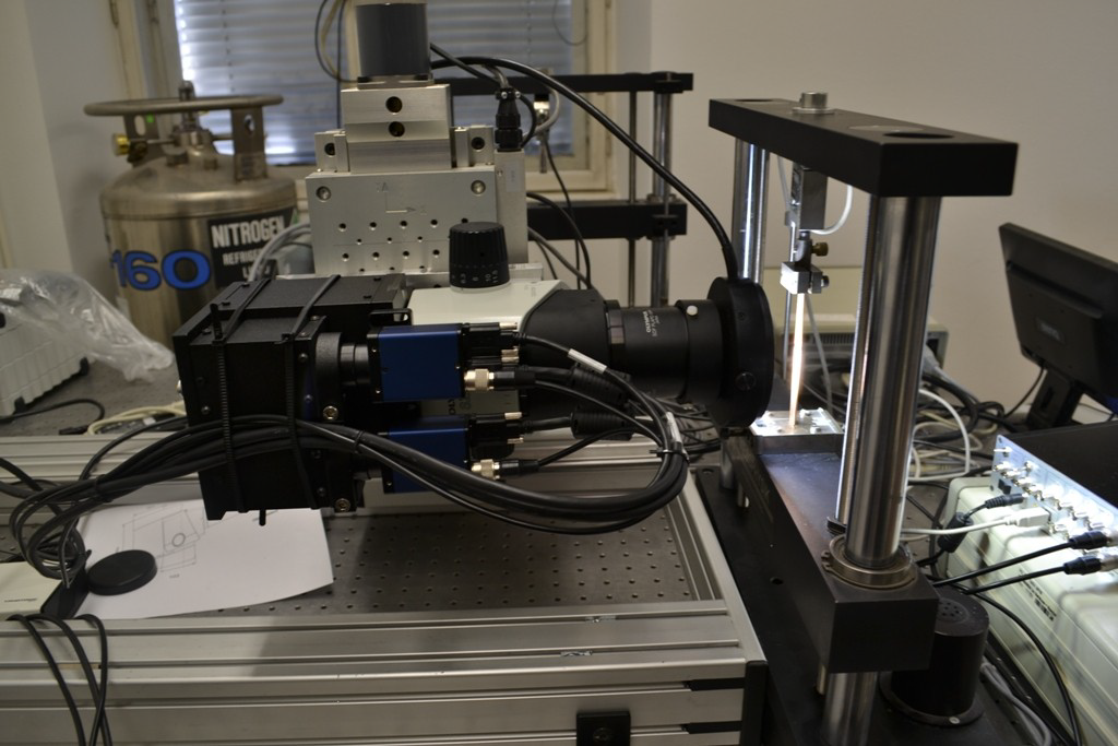
Stereomikroskop

Image 1: Measurement setup

Measurement set up: Stereo microscope mounted on x-y-z-microtable (backside) and tensile machine (right).
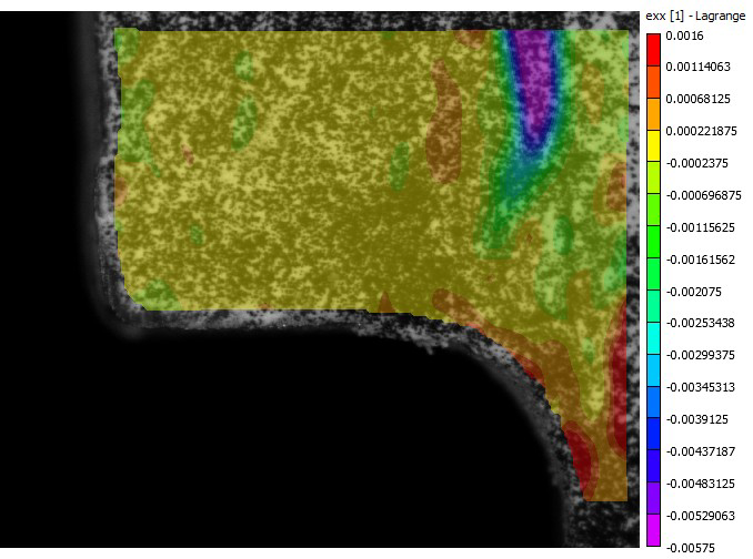
Stereomikroskop2

Image 2: Strain in x-direction

Stereomikroskop3

Image 3: Strain in y-direction

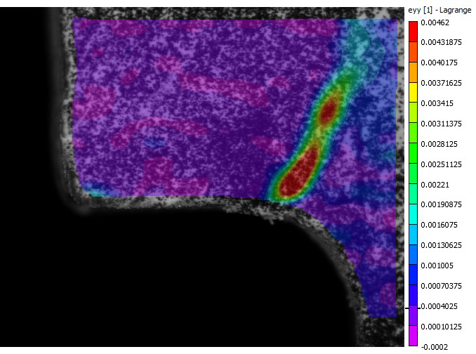
Strain distribution of a half cut capacitor-chip (left part) and its soldering area (round section). The board is under
bending load. The board is vertical on the right sight of the image. The local red area is showing a crack in the
soldering part. Image area approx. <2mm.
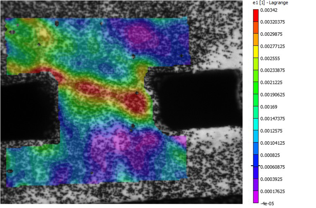
 

Lötkugel

Image 4: The main strain of measuring a solder ball d=300µm under horizontal shear stress is shown.

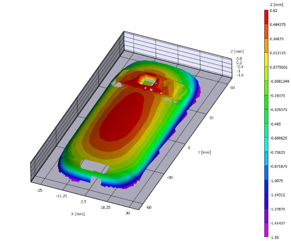
 

Operation mode analysis on a mobile phone during vibration alert

Nokia3

x

Reference coordinates and contour of the mobile phone.


x


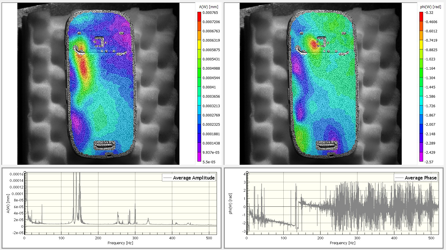
This article describes the measurement and analysis of the operation deflection shapes and rigid body vibration motions of a mobile phone excited by its vibration alert. The mearurement is done, using a non contact, 3D, full-field, high speed stereo image correlation system in combination with the new Vic-3D FFT module analyzes the recorded deformation data in the frequency domain by phase-separation method.

Nokia

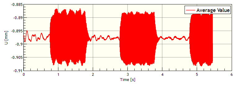
The measured deformations and displacements during the vibration alert are evaluated against the reference state for each stereo image pair. In this case the recording time covers about 5,5 seconds with 1000 FPS corresponding to about 5500 single measurements.

The following figure show the average vibration amplitude U.


Nokia2